Parts / Girth Gears and Pinions
Girth Gears and Pinions
Quick answer
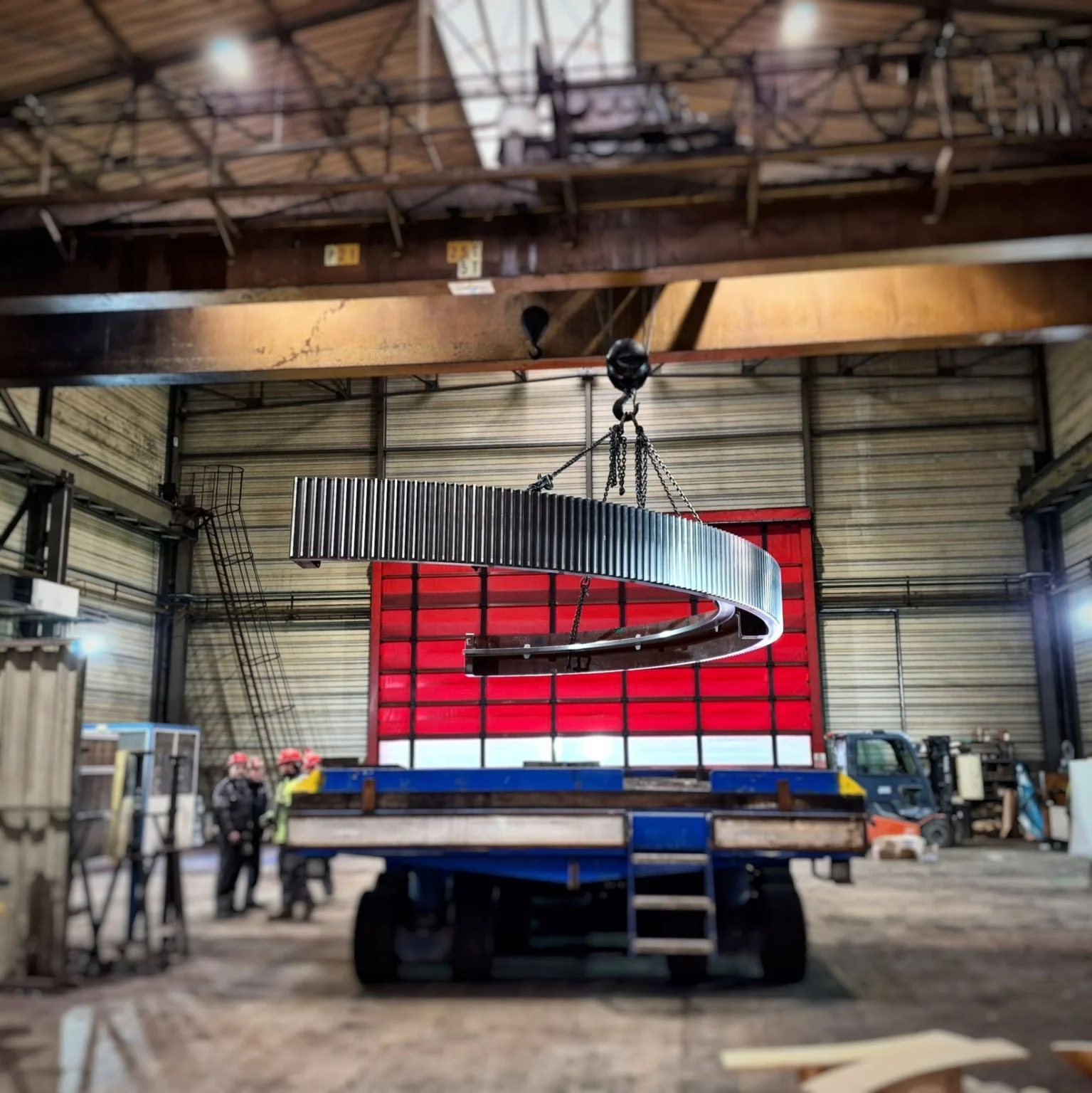
A girth gear is the large ring gear that wraps the shell of a grinding mill, kiln or dryer and turns it. On large diameters it is made in segments, bolted together at the tooth roots. Monmet supplies girth gears up to 12 m in diameter, along with the mating pinions, in cast or fabricated construction.
What the part does
The girth gear is the final drive stage. A motor and reducer turn a pinion, the pinion meshes with the girth gear, and the gear carries the whole rotating mass of the mill or kiln. It is bolted to the shell on a flange, or spring-mounted where the equipment runs hot and a rigid flange mount cannot survive thermal growth. The thing that makes a girth gear difficult is that it is not a rigid gear. A compact gear carries its own stiffness. A girth gear does not — it borrows its structural backbone from the machine it bolts to, and that backbone does not exist while the gear is being manufactured or handled. Every stage of production has to account for a large, flexible ring that deforms measurably under its own weight and under the force of whatever is holding it.
Why segmented gears are a different problem
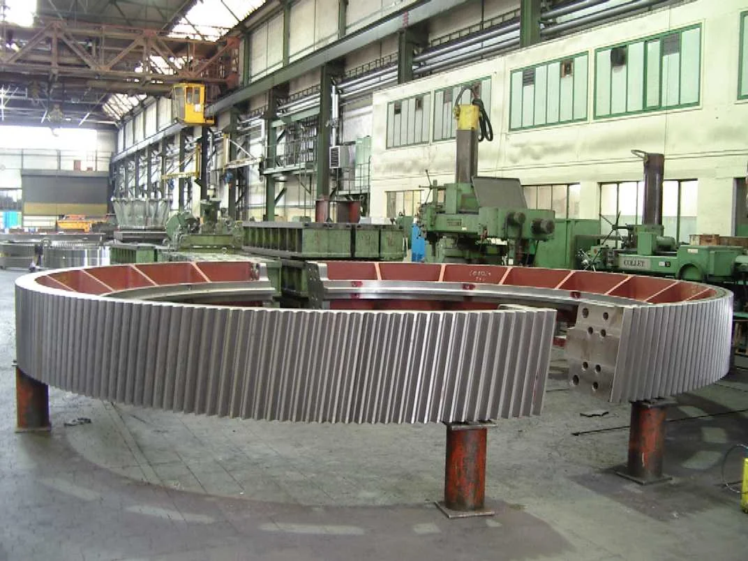
Past a certain diameter, a gear cannot be poured or forged in one piece, so it is made in halves or in four to six segments, split at tooth roots and bolted through the joints. That introduces three problems a one-piece gear never has. Each segment comes from a different pour and is heat treated and stress relieved on its own, so no two segments are metallurgically identical. Small differences compound over an arc tens of feet long. Cutting the teeth releases stress that earlier processing built up, so the gear physically moves after machining. The answer is to machine it twice — semi-finish the joints and turn the blank, then cut the teeth, then verify the joints open and close correctly. The joints are the most highly stressed region of the whole gear. If a joint sits open at the tooth root, the leading tooth can heel over under load, and failures tend to show up in the first two teeth on the trailing side.
How it fails
Wandering tooth contact and uneven load distribution, usually traced back to runout rather than to the teeth themselves; pitting, spalling and scuffing on the flanks, driven by contact pattern, lubrication and alignment; joint problems — bolt relaxation, fretting on the joint faces, a gap opening at a tooth root; root cracking, which is the failure that ends a gear rather than wearing it; pinion wear running ahead of the gear, since the pinion takes many more load cycles per revolution; distortion introduced by handling. Lifting a finished gear can load the joint hardware well beyond service loads, so joint alignment is worth re-checking after any move. A useful way to think about it: excellent material and precise teeth are worth very little if the pitch cylinder wobbles once per revolution. Geometry of the blank governs the outcome as much as the tooth cutting does.
How Monmet supplies them
Monmet supplies girth gears up to 12 m in diameter and the mating pinions, for grinding mills, kilns, dryers and coolers, through its worldwide network of foundries, forge shops and machine shops. Gears are supplied cast or fabricated, in one piece or in segments as the diameter requires, and Monmet manages the work from engineering drawings through to finished machined components. Gearbox overhaul, gear cutting and rebuilds, and complete drive train components are supplied through the same network. Where drawings are unavailable, the existing gear and its interfaces can be measured and documented into a manufacturing drawing set. Monmet is ISO 9001:2015 certified by SGS.
What Monmet needs to quote
Equipment type and size — mill or kiln, diameter, length, installed power, speed, direction of rotation; gear outside diameter, pitch diameter, face width, number of teeth, module or diametral pitch, pressure angle; tooth alignment — spur, single helical or double helical, and for helical the hand and helix angle; mounting arrangement — flange mounted or spring mounted, with the flange bolt circle, bolt count and hole detail; number of segments and the joint design, including the alignment hardware used and whether joint faces are cut on the helix angle; structural section, and whether the existing gear is cast or fabricated; the mating pinion: tooth count, face width, centre distance and mounting — and whether the pinion is being replaced at the same time. Gear and pinion wear as a pair, and a new gear meshing with a worn pinion is a common way to lose a replacement early. Also useful: measured runouts on the installed gear if you have them, plus contact pattern photographs and any history of joint or root problems; lubrication type and application method, and the guard and spray system arrangement; crane capacity and access at site, which determines segment count and shipping split.
Frequently Asked Questions
Related Parts
Start Your Project
Request a Quote
Talk to our specialists and find other ways of forming and shaping metal. There are options aside from casting and forging, such as metal spinning, extrusion and drawn metals.
Get in Touch
Let's discuss your next project.
Send us a drawing, a sample photo or the part description. A Monmet specialist will review it and follow up with a quote.